Bamboo Tips - Contraptions Bevelers |
|
< Home < Contraptions < Bevelers
Here are some pictures and/or drawings of bevelers from various makers. If the name of the submitter is underlined, you can go to the submitter’s web site. If you click on the picture of the beveler, you will go to a page that will give more explanation of the beveler.
Martin-Darrell
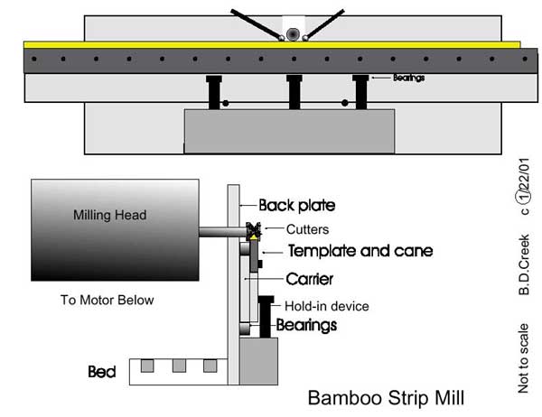
Brian Creek
Following is a narrative of email conversations that Brian had with Chris Lucker regarding this bamboo mill. Very nice job on the drawing. Few changes:
You need some kind of steady tensioner to hold the carrier against the backbed. I have used such things as a block of aluminum locked against the carrier (with relief for the template bolts milled out) to a spring loaded gizmo that forced shaper bearings against the carrier. It all works. Remember -- do not get scared about your inability to get everything perfectly square -- it does not need to be. But it must be repeatable! Just think about it and you will understand. Great drawing. Your hold downs may be Dickerson-style teeter-totters or Wes Jordan-style direct downs -- does not matter. I use two inch long blocks of that slippery plastic stuff now instead of rollers. Ed Hartzell gave the blocks to me. Rollers are easier to make out of 0.75 brass or aluminum or delrin though. Keep your hold-downs a close as possible to the cutters. I did not tell you, but I am sure you understand that my design uses a head that raises or lowers. You may use this design for a Dickerson-style mill, but the backbed must raise/lower, and half the time the carrier may move with gravity. My current milling head moves up or down 0.100" with one full turn of the micrometer adjustment crank. It's part of an old milling head or DuMore Grinder or something. Chris Thanks so much for your kind assistance! I would never have thought to go this route. I've been looking for something that weighted 100 tons to dampen vibrations. I use a rough beveler now made from aluminum and a router. I still spend a fair amount of time straightening and pressing nodes, but it is such a liberating machine! Must cut 4 hours off of building a 2/2 rod. You are smart to worry about vibration. Here's what I have learned. A cast base dampens vibration. I currently use a small cast table saw for my base. It is surface ground and vibration resistant. Secondly, drop a bag of sand or buckshot wherever you may fit one. Sure it sounds hokey, but loose heavy stuff dampens vibrations and adds portable weight to an otherwise light mill. Thirdly, let some vibrations happen. Why do you think they have used 62 degree cutters all these years? Not to make 62 degree strips. Vibration will lessen 62 degree cuts to something less, I can't tell you what, but you understand the idea. Vibration will lessen 60 degree cuts to something less too -- now you know that's bad. Ed Hartzel sold me my 62 or 63 degree cutters. They are currently on loan to Bob Summers. I believe that Winston uses, or at least used, Ed's cutters too. He is in Portland. I have his number at the office. When I looked to having carbide cutters custom made years ago they cost $650 a pair. Ed has a dozen sets made at a time and reduces the cost tremendously. Ed is a good mill man, by the way. Talk to Charlie Jenkins too. He likes mills more than making rods. You know him. He's in Colorado. Talk to Charlie -- not his son. I haven't talked to Charlie for maybe ten years, but he's a good guy. I don't know what you mean about adjusting the head vernier? I know what a vernier calliper is, but what are you asking. Please ask again so a dummy like me understands, and tell me how to use the term correctly so I can communicate with machinist guys better. Thanks. Your question about using the same template for different sized rods is easy to answer, but maybe misleading too. I build rods like EC Powell, except I taper both sides of the strip. You can make rods tapering your rough 60's on one side only. The Powell, Maslan, Yerxa and LaVoy tradition only tapered one side of the rough 60's. Anyway, I build B tapers and A tapers that are simply formulas that may be used for any sticks -- i.e. 0.009" every six inches for a B9 or 0.008" plus an additional 0.000125" per every six inches for an A taper. I do use the same eight templates for everything. I have a real Paul Young Midge (Young's actual taper formula he used at least once in 1954), a Paul Young Perfectionist ((Again, what Young actually intended to cut, not some measuring guesswork); a Paul Young Princess (the most overblown rod I know of -- if it was so great, why did Young only make six or nine of them?) and EC powell B9, B8.75, B8.5, and a couple of A tapers. I did not understand your question about the orientation of my mill parts, but I will lay the parts out this way. Imagine we are looking at the cross section from one end. This is what we see looking left to right:
Add dust collector and auto feed you can disconnect. Auto feeds really impress people though. Chris Also, do you need 3450 rpm rather than 1750? The theory behind 3450 rather than 1725 is that your belts will cause less vibration. I really don't like to have a small pulley on my spindle -- too much vibration caused by a belt going around a tight corner. But hey, Dickerson used a 1725, at least it appears so from the pulley ratios I have seen in his pictures. I ran the Dickerson mill when it was owned by Tim Bedford -- the guy who bought it from Dickerson, and the guy Jim Schaaf got it from -- anyway, Bedford had already switched out the motor saying that Dickerson always meant to do it. Are you calling that vertical graphic with the numbers on it a vernier scale? I guess that makes sense. The surface grinder I parted out had a micrometer crank on the grinding head. Does your bed raise up and down or does the hed move up and down? Does not really matter. Just mount a dial indicator or two if you want to double check. Anyway, yes, to answer your question. Just mount this backbed etc and go. Ed Hartzel may be reached at 503-286-8114. I would lend you my carbide cutters to look at, but Bob Summers is using them, or at least trying them. Ed can tell you what size shaft hole he can come up with. Right now he is making one inchers. Don't jump into buying a new surface grinder. Go to the junk machinery shop in the nearest depressed metro area where they are trying to sell off all the antiquated non-cnc machinery. I don't know if you have a good lathe, or not, but you may be able to get a good deal if you buy a ten inch quick change Logan lathe or a 10 inch South Bend that takes 5C collets and have them throw in a milling head or surface grinder head. Remember, you can buy a parted one because you don't need the auto feed, unless you want to use the machine to make mill parts. By the way, how do you make a lathe without a lathe? Chris Note: All information listed here is Copyrighted 2002 by Brian D. Creek
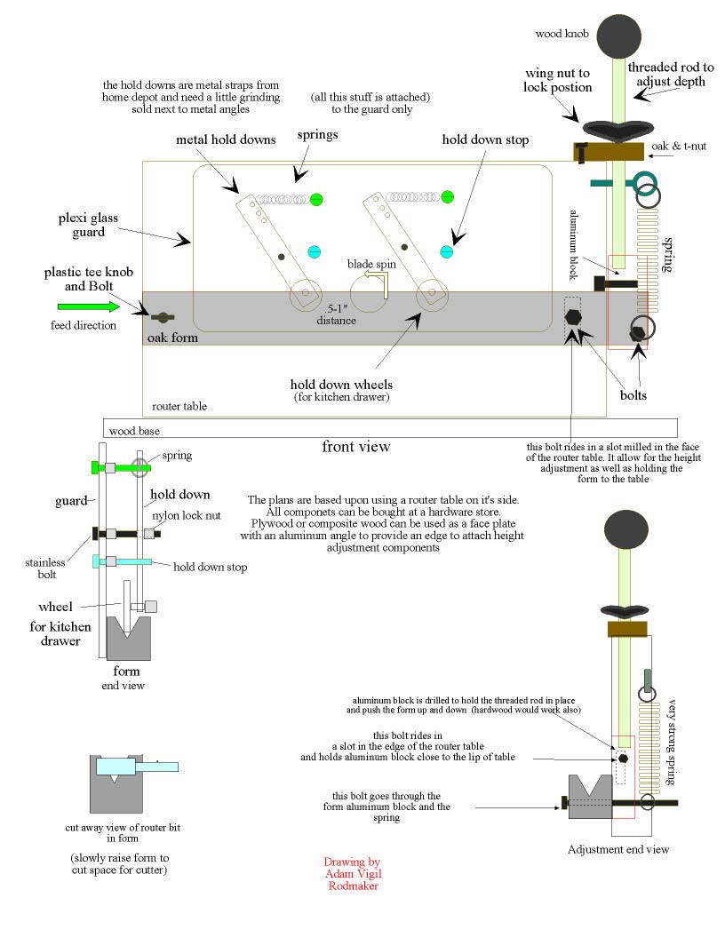
Don Schneider Power Planer Beveler Forms
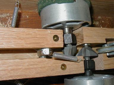
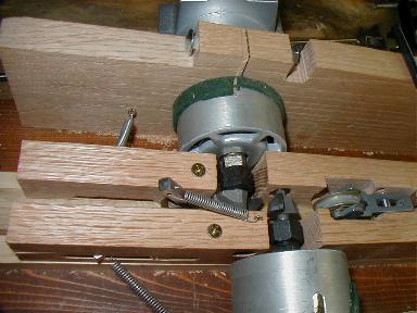
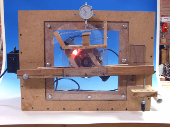
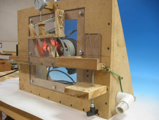
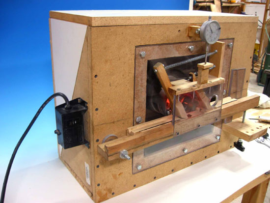
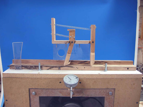
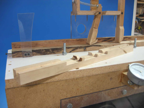
Ralf Ladda’s explanation of Walter Brunner’s mill. Here is a pdf file that Ralf sent. Explanations to Pictures 1 and 2: A = Bed The strip is inserted into the power feed (D), which consists of a number of rotating rubber pulleys. The Pulleys should be made with an adjustable spring mechanism, so they will fit different strips with various widths. The power feed is driven by drive belts with a motor with an adjustable speed. When the strip passes the first micro switch (F) in front of the Cutter (B) the cam (C) which is located underneath the bed (A) will start turning. The motor which turns the cam has to have an adjustable speed as well. The cam will lift the bed/strip into the cutter as the strip is pushed forward by the power feed. The amount of height gained by the bed is dictated by the cam's shape. As soon as the end of the strip has passed the micro switch which is located behind the cutter the cam will stop turning - this means that both micro switches have to be connected to the motor of the cam to either turn it on or off. As you can see the cam has a very special shape, which has to be calculated according to the taper of the butt- or tip section. This means you have to have a cam machined in a shop for each butt- and tip section taper. You have to correlate the speed of the cam and the speed of the power feed. Exactly at the point when the front of your strip enters the cutter the cam has to start turning and exactly when the strip leaves the cutter the cam has to stop turning and should have made one full turn (actually not really one full turn - it has to turn from the lowest point of the cam to the highest point, I'm my picture this would be about 270°). Walter Brunner has solved this problem by installing a little green light which comes on, when the strip passes the first micro switch and which turns off when it passes the second micro switch. Just below this green light he has a little disc with a red dot painted on it. This little disc is connected to the cam and turns at the same speed. Another yellow dot is painted on the outside of the little disc. When he starts milling he aligns the two colored dots. Now the little green light comes on (when the strip enters the cutter) and the red dot starts turning. When the green light turns off (the strip has passed the cutter) the two colored dots should be aligned again (see picture 2). This is a matter of trial and error and it requires two motors with variable and adjustable speeds (one for the power feed and one for the cam). I didn't draw the hold downs for the strip (spring mechanism), so you have to add them as well.
Tony Spezio’s Quad Beveler
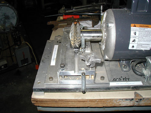
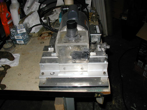
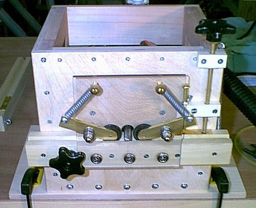
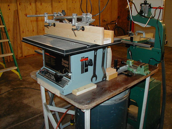
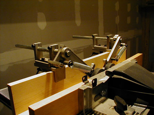
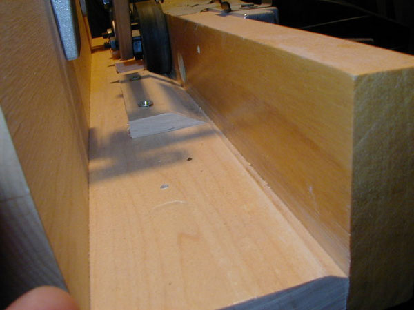
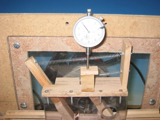
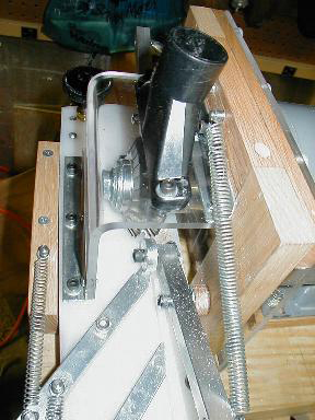
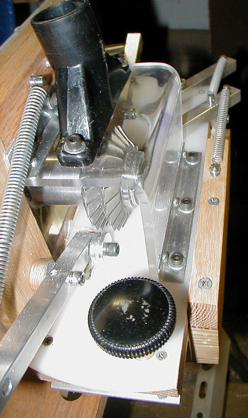
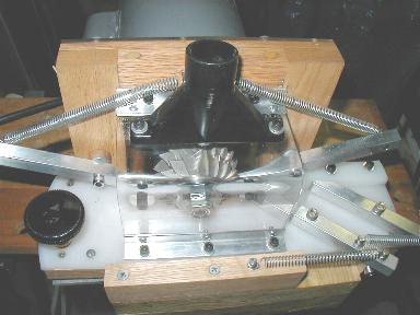
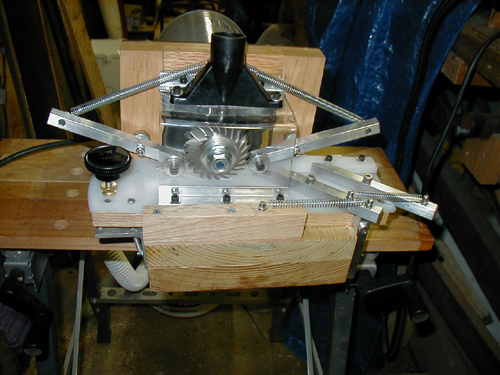
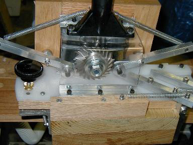
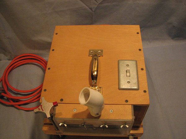
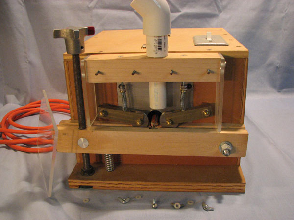
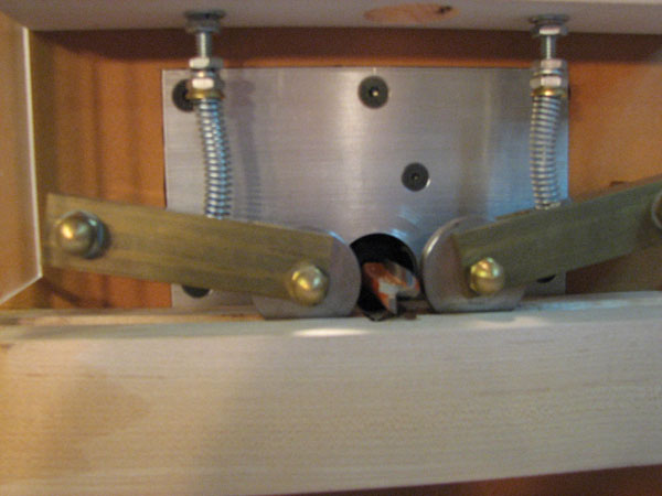
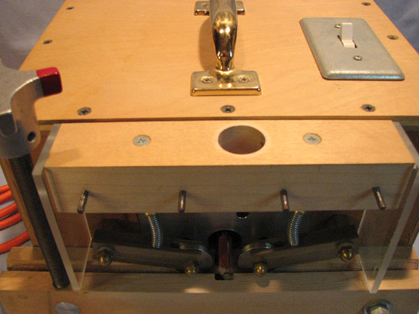
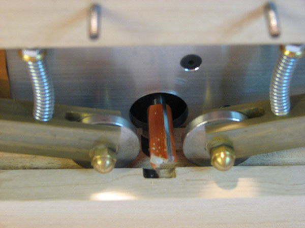
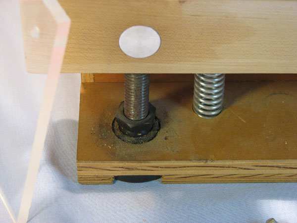
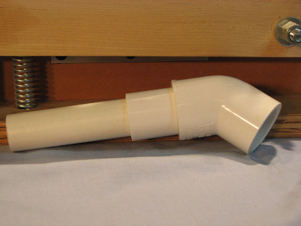
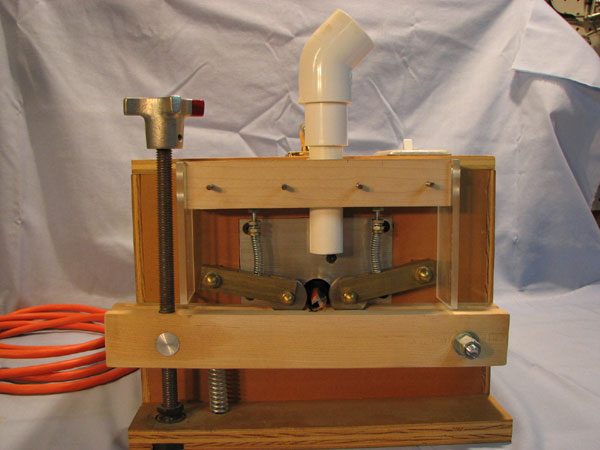
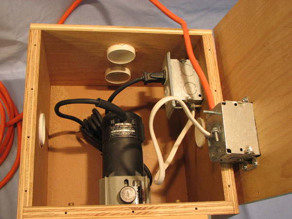
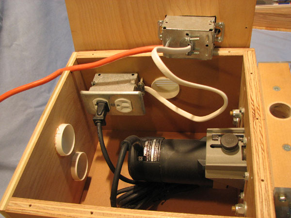
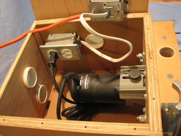
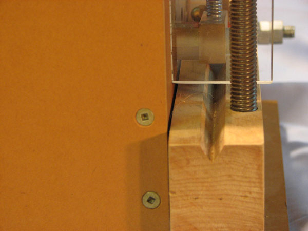
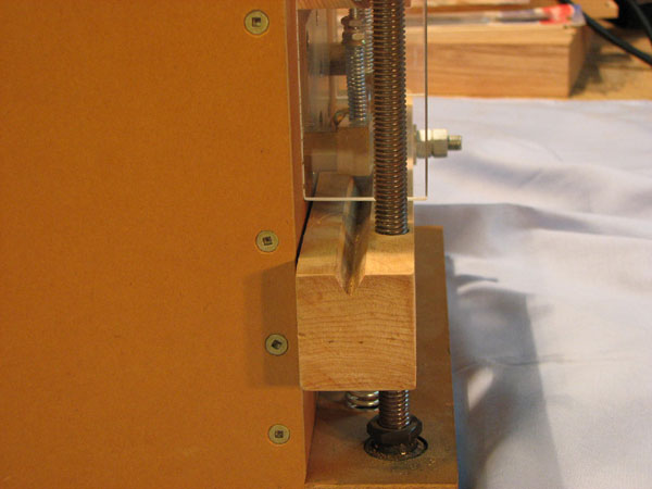
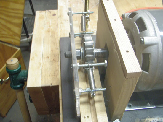
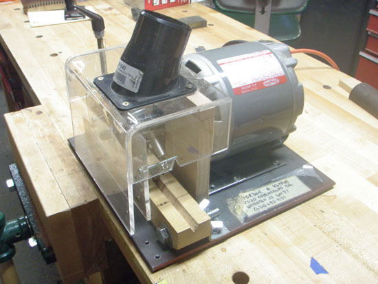
Chad Wigham’s Beveler
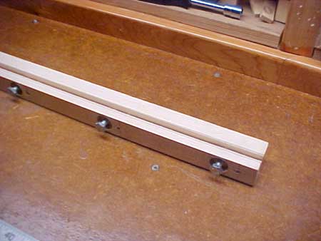
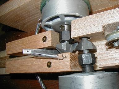
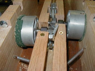
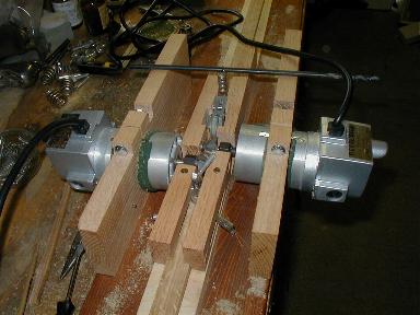
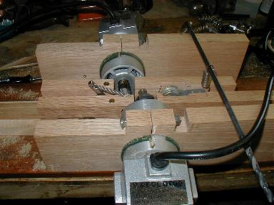
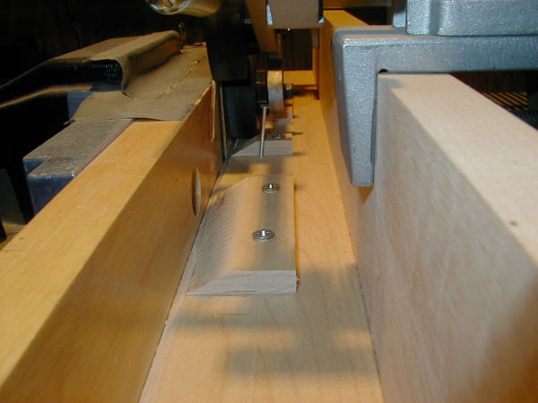
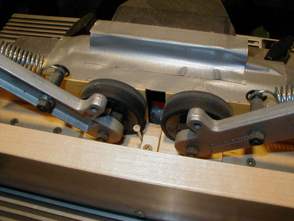
Inbound
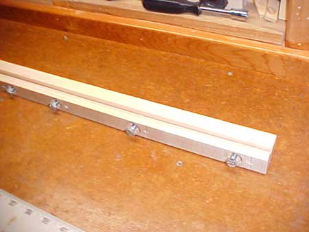
Outbound
The roller guides are manufactured as anti-kickback hold downs for table saw application. To configure in the beveler application, they have to be changed on the axles and the ratchet/anti-kickback dogs removed. The spring tension is adjustable, and holddown pressure is very good. It's best to square up the stock so it is uniform and the nodes flattened, so each pass thru is smooth. Sections will still requires planing as there will be hard & soft spots throughout each piece, but it saves a heck of a lot of planing strokes. The sections come out at a true 60 degrees which pays off in final planing. Roller holddowns are item #96-974 @ $49.99 through Woodworker's Supply catalog.
Denny Dennis’s Beveler
Tony Spezio’s Hex Beveler
Brian Smith’s Mill This is a combination of a Milward and Whitehead design with some input from my friends at Corens.
Gordon Koppin’s Beveler
|