Bamboo Tips - Tips Area |
|
< Home < Tips Area < Form Setup < Depth Gauge Setup
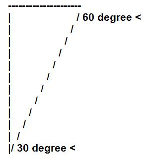
When you set the indicator to zero you are using the ACTUAL point and when you measure the depth you are using a "virtual" point (there's that computer term again). If the point has been dinged the shoulders won't meet at the actual point and when THEY tell you the depth of the groove there will be a discrepancy between the actual depth and the virtual depth (the indicator thinks the surface is farther away than it really is). I guess it would be fair to say that your depth reading will be accurate but your initial zeroing will have been off so that the difference will be computed incorrectly. The use of the calibrator sets your zero using the shoulders of the point (what you're actually measuring the vee with) so that there is no possibility of the zeroing and the measuring being out of synch with each other. This will involve seeing (one-half) the tip as a 30-60-90 degree triangle and using trig to find what the indicator "THINKS" is the point's position. I'm going to try to show a diagram here but I don't have much hope for it. The top is 1/2 the hole's width (1/16" in previous example) The vertical side is the depth the SHOULDERS will say the groove is (the diagonal is the shoulder of the point). If you set your indicator on the form and call THAT zero when it sits there, your (non)point and shoulders will be in synch with each other. The vertical length of the triangle will be 1.732 times the width of the top (of our triangle -- not the hole (Trust me, I've been teaching this to freshmen for thirty-one years)), so it'll be 1.732 X (1/16) or 1.732 X .0625 or 0.10825". This is of course true ONLY if you use an accurate 1/8 " wide hole. Change the hole width and the geometry still works but you'll need to compute the half-width of your hole times the 1.732 yourself. If this helps let me know; if not fire back your questions. If the picture stinks I have a feeling we're going to be in a real pickle though. (I'll give you instructions on how to draw it yourself) Rereading it I see it's necessary to mention the "calibrator" is a small block of metal with a 1/8" hole drilled to a depth such that the 60 degree point can't possibly hit the bottom (will rest on its shoulders). (Art Port) Lacking a gauge block with a "reamed hole" one can use a caliper to accomplish the same. Simply set it at 1/8" (or what ever diameter. you choose to work with), set your indicator on it and proceed. (Gary Heidt)
The easiest way I found to set your depth gauge to 0 is to set you calipers to .1155. Set the 60 degree point in the .1155 caliper gap with the indicator block flat on the caliper blades. Rotate the face of the dial indicator to zero, tighten the face set set knob. I have had no problems with getting the right depth in the forms using this method. I do not take credit for this, a machinist friend put me on to it. If you set the 60 degree point at .1155 and then set the point on a flat surface and the point is perfect, you will see that the dial will be at zero. If the dial is not at zero and is say .002 then the 60 degree tip has a .002 flat spot on the point. There would be that much error on a flat surface and along the whole 60 degree angle. The only time you will get a true measurement is if the point is absolutely perfect. Doing the .1155 assures that you will get a true setting on your forms. Hope this helps you understand what is being done. (Tony Spezio)
John Bokstrom explained setting your depth gauge something like this: Be sure you do not bent, dent, blunt the tip of your 60 degree tip. Gently place your dial indicator on your metal form with the 60 tip touching the flat area. Your base should be adjusted on your dial indicator to allow it to be able to this. When you have your dial indicator in its base with the tip on the flat part of the form you will set the face of the indicator to zero with the needle. Tighten the face and now you are at 0. If you are using rods to measure just take off the tip and repeat the procedure above. You can then place the 60 tip in the groove of the form and measure the depth. You typically will be reading it backwards. On a lot of indicators it is the inside red numbers. (Adam Vigil)
To make a calibration jig, drill a hole through your forms, tip side to butt side. Ream the hole to .100" With a 60° tip on your DI place the tip in the hole. Set the DI to .0866" Calibration done! Advantages:
Depth gage calibration cannot be trusted if you use the tip. Set your calipers to .1155" open and the 60 degree point will fit just right such that dial should read .100". (Ralph MacKenzie) What it means is that to calibrate your depth gauge, instead of setting it down on a flat surface and setting the dial to read "zero", open the jaws of your dial caliper to .1155". Then, rest the depth gauge on the open jaws with the 60* tip in the open jaws, as if it were being set into the groove on your planing form. Now set your depth gauge to read .100" and it is properly calibrated since the geometry is such that a .100" deep V groove is .1155" wide across the top. Nearly always, the tip on the 60* point gets micro-smushed, and when you set it for "zero", it really should be .002" or something like that. By calibrating on the sides of the tip, you avoid that problem. Don't know who came up with this originally, it's back in the archives somewhere and I found it very handy. (Ralph MacKenzie)
I need some info on setting up my gauge to set up my planing form. The difficulty is that the readings do not coincide with the functioning ability of the form itself. In other words, I’m unable to get the form down to less than .050. I've been told that my form is good, given that it has stations tip section every 21/2". Further, the gauge is a 20.00 dollar special from Starrett, with a homemade wood base etc., equipped also with the 60 degree tip. Could someone out there give me some indication as to where I'm going wrong. (Jim Switzer) Being an absolute beginner, I'm a little hesitant to post this to the entire list. But, (gosh) it seems that many questions are getting answered off list these days when, in my case, I receive better advice when I take the chance of being told I'm wrong (again)! I've learned to anticipate it and thoroughly enjoy the mentoring! [:-)] Take a look at Chris Bogart's article on using drill rods to calibrate a depth gauge. Try measuring the tip with a small drill rod and see if you can get past the .050 problem. It may be your indicator point or the form. Chris explains both in the article. (click Rodmaking Tools Info on the left.) This will allow you to calibrate your indicator to an accurate base setting if that is a problem. For a dial indicator base, I purchased a "123 block" from a local machinist supply house. These are "Swiss cheese" blocks that are used as spacers by machinists. They are drilled and threaded at 3/8" and are accurate to within .001. ("456" blocks are within .0005 for about $40). The 123 block makes a nice stable base for the indicator. My indicator fits nicely in the 3/8 hole. I secured it with some 3/8 inch coarse thread bolts. It looks a little unorthodox, but works great and I didn't have to wait on mail order. They came two to a set - the other block can be used to make an accurate jig for a lathe bit. The 2 blocks cost about $10. (Mark Evans)
A note to rodmakers who suspect their dial indicators may not be giving true readings; I have been using one from Golden Witch and noticed my tapers were coming out a bit thin; I then recalled a chapter in George Barnes' book 'Flyrods Galore' pp. 118-123 describing the use of a tool he made to hold the indicator over the forms so that he could measure the height of a drill bit or blank of known diameter laying in the grooves of the form and then using a simple formula calculating the true depth; I have found a device you can use for this purpose; it’s called a one-way multigage and sold thru Woodcraft (800 225-1153) cost $80; refer to planing form issues March/April 1994 #26 and May/June #39 for specifics on the math; I found this method to be easy and reliable and a quick way to true up your dials; any comments? (David Haidak) Some time ago, some clever person on this list told about setting zero on a dial gauge using the .1155 gap in your calipers. I am no engineer, but it revitalized my form setting in terms of accuracy, and I cannot fault it as a useful technique. (Peter McKean) I find the easiest way is to set my calipers at .1155. Insert the point and set the block flat on the caliper jaws. Zero the gauge and you are there with no figuring. This has worked for me for almost 4 years, real simple and accurate. (Tony Spezio) I have my forms sitting on 1" blocks to elevate it off the bench. I set my calipers to .100" and lock it. Using a spring clamp with a rubber finger tip protector on one jaw clamp it to the forms. Set the DI with 60° point in the gap and set the dial to .0866". Tony is absolutely right, setting the caliper to .1155" and setting the DI to 0/.100" amounts to the same thing. (Don Schneider) I don't know who posted this but what he said was set the caliper opening at .1155, set the 60 degree point in the .1155 gap with the indicator block flat on the caliper blades, rotate face of dial indicator to zero. (Patrick Coffey) I've seen a lot of threads on calibrating with this method and I understand that it works, but as a person who has been trained/worked in Quality Control I prefer using gage blocks, or index blocks when doing any type of calibrating. My thoughts are that this method relies on the accuracy of the caliper and the person using it and I’ve seen too many people use calipers incorrectly. Once again just my 2 cents worth of thought. (John Freedy) You are not actually "measuring" anything, just using the calipers to provide a reference. For the average person, the gap in the jaws will be more accurate than anything else they have available. Granted, it does rely on the accuracy of the calipers, but they are the same calipers most people will use to measure the finished strip. If they don't read correctly, the strips will measure over/undersized regardless of what method is used to zero the indicator. Using a flat gage block to zero the indicator to a reference surface does not work because it relies on the point. The ideal solution would be to use a block with a precise hole in it, or a ground block, as you state, but many of us don't have those lying about. (Larry Blan)
To assist myself in checking or calibrating my DI on one set of forms I made I machined a very accurate hole, .100", in each side of the forms near the butt end. I choose the butt end because it seemed to me this area of the form surface would get less plane traffic. So, no matter which side of the forms you are working on to check/calibrate/set the DI with a 60° point. Set the point in the hole and set the DI to .0866" I check the setting with the other methods and if the readings are the same that it close enough for me. (Don Schneider)
I was reading the messages in the archives about this subject and am now confused. In one post it said to set the 60 degree tip on the top of the forms and set the indicator to 0. Another post said to set the gap on a caliper to 0.1155" and set the tip in it then set the indicator to 0. Now it seems to me that these would give very different results since one is set ot a flat surface and another to a depression 0.1155" wide. Which is correct? Another method was to use a 1/16" drill rod placed in the forms, open them until the top of the rod is even with the top of the forms. This will result in a depth of 0.09375". Place the tip in the forms and set indicator to -0.09375". Shouldn't the indicator be set to +0.09375"? (Larry Puckett) The 60° point on your dial indicator can get crushed in time. Which means setting the point on the table or on your forms and setting the indicator to zero will have an error in your reading. So to keep this from happening set your caliper to 0.1155 and set the tip of the dial indicator in the gap, then calibrate the dial indicator to 0.1000. Here is the math. sin 60 x 0.1155 = 0.1000 (rounded of course) (Robert Holder) I've seen a previous post that said set the dial indicator at 0.0000 after putting the point in calipers set at 0.1155. Which is correct? 0.0000 or 0.1000 (Ed Riddle) I don't think it matters. I set mine to 0.500, because it was almost there anyway. You are measuring the difference between the "zero" setting and the depth of the groove. (Neil Savage) Maybe I can clear this up. I have been using the .1155 method for setting the depth gauge for the 3+ years since I started making rods. Have posted on this a number of times. Setting a perfect point on a perfect surface and setting the indicator at ZERO is ZERO ( no depth). In our case the points are not always perfect (as would be my aircraft points) and the form surface is also not perfect. The amount they are off will give you some discrepancy in your reading if the dial is set to ZERO with the point flush on top of the form. In using the .1155 and setting the point on that space, it relates to .1000 deep. The Dial is set to ZERO but in fact the depth is .1000. Now when this point is set in the form groove, any reading below the Zero Mark is a minus .1000 and when the needle passes the ZERO mark on the dial, the reading is plus .1000. Using this method will also not be perfect if care is not taken to set the calipers right on .1155 I have recently had a reamer precision ground to .1155 and had a 1155 reamed hole put in a plate. I check my setting from the caliper with the reading I get from the .1155 hole in the plate. If I take care and set the Caliper right at .1155 the readings are exactly the same. So to answer your question, yes the dial is set at zero but the point is .1000 deep in the caliper jaws. (Tony Spezio) I can't use the caliper method. I've got a V-block on one of my caliper and I'm not that certain that I can calibrate the other that well. I also find it difficult to hold the depth gauge and base on the caliper. A small amount of movement can mean a good bit of change. In other words, I'm all thumbs. What I do though is close to what Tony talked about in his email. I have a small piece of metal with a 1/8" hole reamed into it. Off the top of my head, I don't remember what the depth is for that (I have it written on the indicator at home). My other problem is that I use a digital indicator so it isn't as simple as rotating the bezel to the proper setting. I've got to carefully slide the indicator up and down in the base. Time consuming, but doable. (Tim Wilhelm) Try This: Adjust the caliper to .1155". Clamp the caliper to your forms with a spring clamp. I have my forms elevated off the bench with small blocks when in use so that spring clamps can be used to hold strips while planning. Now that your hands are free, place the DI with a 60° point on it in the gap. Adjust the DI to read .100". If I wish to check the calibration of the DI later while planing: Drill a hole near the butt end of your forms on each side. Ideally the hole should be .1155" diameter To check the DI, simply put the point in the hole and see if the DI reads .100". IF not, adjust the DI. It really doesn't make any difference what size the calibration holes in the forms are as long as you know what the DI should read when the 60° point is in the hole. (Hole diameter) x .866 = What DI should read. (Don Schneider) The difference that's bothering you is that when you set the point of the indicator on the form, you're measuring using the tip itself; when you use the indicator to measure your depth-of-form, you're using the SHOULDERS of the point. The shoulders meet at a VIRTUAL tip/point, but the actual tip of the point is usually rounded, either due to manufacturing specs or to manhandling by the user. The drop-it-in-the-hole method of setting ensures that the shoulders are measuring accurately, since there's no bottom in the forms for the actual point to hit and register. I had saved the original explanation (It came up so often) but just switched to a new computer and no longer have it, so I'll ask you to see if you can locate it in the archives, so I don't have to type a treatise in geometry again. (Art Port) The virtual reality wasn't what had me stumped, it's the fact that there are conflicting posts in the archives. One says to set the caliper to 0.1155" then set the indicator to "0" and the other says to set the indicator to "0.1". Using your math I see that the 0.1" value is correct not "0". Thanks for the math and geometry and trig refresher. (Larry Puckett)
|